

As the demand for secure and efficient embedded solutions continues to grow, manufacturers are integrating secure subsystems into System-on-Chip (SoC) architectures. Professionals such as engineers, security architects, systems architects, and product developers involved in embedded security, secure elements (SE), SIM cards, and hardware security modules (HSMs) for 5G connected devices—such as smartphones, IoT devices, and automotive applications—need to understand Protection Profile 0117 (PP0117). The article aims to elucidate how PP0117 establishes the security framework for integrating secure subsystems into SoCs, highlights its differences from PP0084, and discusses its endorsement by the GSMA, the global authority on mobile security.
What is a protection profile?
A Protection Profile (PP) is a security guideline document that standardizes the development, integration, and evaluation of security mechanisms in hardware and software. PP0117 was specifically designed to define security requirements for integrated secure subsystems in SoCs, such as embedded SIMs (eSIMs) and secure elements (SEs).
Before PP0117, Protection Profile PP0084 was widely used for stand-alone security components, such as SIM cards and secure elements. However, integrating these components directly into SoCs presents new challenges that PP0084 does not address, such as defining security boundaries within complex chip architectures. PP0117 was developed to overcome these challenges, ensuring strong security for integrated secure elements (iSE) in SoCs.
Introduction
Protection Profile 0117 (PP0117) is a protection profile designed to facilitate the integration of a secure subsystem (3S) into large-scale System on Chip (SoC) architectures.
Prior to PP0117, Protection Profile PP0084 was used to evaluate stand-alone security components such as secure elements (SE) and SIM cards. However, when integrating the logical functions of SE or similar devices into a larger SoC, the implementation constraints render obsolete some of the methods and requirements of PP0084.
Secure Sub-System in System-on-Chip (3S in SoC) Protection Profile was developed to address the security of integrated solutions and provide the industry with a unified set of clear and assessable security requirements to be fulfilled.
This PP was developed under the Eurosmart association by gathering the technical committee members, including developers, labs (ITSEF), and certification bodies. The certification body selected for PP0117 is the German Bundesamt für Sicherheit in der Informationstechnik (BSI).
PP0084 vs PP0117 based designs
PP0084, originally designed for discrete security elements (such as SIM cards and smart card chips), assumes a physically isolated security boundary with strict interface protocols.
By contrast, PP0117 adapts security guidelines for secure elements integrated into SoCs with complex internal and external interfaces. The key differences include:
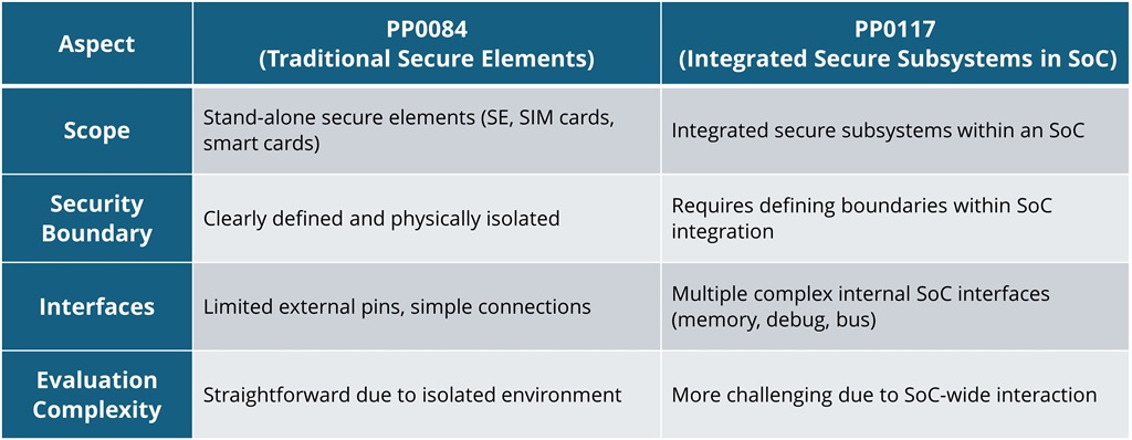
Credit: Winbond
PP0117 ensures that integrated secure elements maintain the same level of security as stand-alone secure elements, while adapting security requirements to the realities of SoC design.
There are several major differences that need to be considered when designing and evaluating a secure subsystem in a large SoC, as opposed to a stand-alone secure controller.
The most notable differences arise from process constraints in device fabrication, such as the absence of embedded non-volatile storage and the difficulty in defining security boundaries. Evaluating an integrated secure subsystem is also more complex compared to a stand-alone device. This complexity stems from the numerous interfaces the integrated subsystem shares with the rest of the SoC, as opposed to a stand-alone device with limited pinouts and strict interface protocols. Consequently, all parties involved in the design, fabrication, evaluation, and utilization of such secure subsystems must adhere to a more comprehensive set of guidelines, as outlined by PP0117.
A standard SE or eSIM is packaged in a small, limited pin-count package. In terms of security evaluation, this small, packaged device constitutes the Target of Evaluation (TOE). Evaluating such a device is relatively straightforward due to its limited range of connectivity and interfacing options. However, in the case of a large SoC, the majority, if not all, of the secure subsystem's interfaces are internal to the die and are seldom externalized. Additionally, there may be extra interfaces that are not typically present in stand-alone security devices, such as memory interfaces, debug interfaces, system bus interfaces, and those used for more advanced functions.
PP0117 is designed to guide the development and evaluation of integrated secure functionality, defining the requirements for such interfaces and outlining methods to assess their security.
PP0117 version 2 and GSMA endorsement
The GSMA (Groupe Speciale Mobile Association) is the global organization that sets security standards for mobile network security, SIM technology, and eUICC (embedded SIMs). In 2024, GSMA endorsed PP0117 as the security framework for integrated eUICC (embedded Universal Integrated Circuit Card) implementations.
GSMA recently published eUICC (embedded SIM) Protection Profile V2.0. This Protection Profile allows for both discrete eUICC and integrated TRE (Tamper Resistant Element) implementations for embedded SIM/UICC implementation. The Protection Profile V2.0 references PP0117 for integrated solutions on top of PP0084 for the baseline requirements of eUICC. The GSMA's support for integrated secure subsystems that implement SIM/UICC capabilities facilitates a higher level of functional integration of handsets and IoT devices into the SoC.
Major PP0117 use cases
The most notable use case of PP0117 is integration of SIM card functionality into SoC devices. The trend of SIM integration takes place in two major verticals – IoT connected devices and mobile phones.
1) Integrated SIM
In mobile phones, the main SoC device integrates as many logical functions as possible. This approach enables a reduction in power consumption, offers better pricing, minimizes board space, and introduces new functionalities. Given that SIM cards essentially function as simple microcontrollers with non-volatile storage for code and data, their integration into larger SoC devices appears inevitable. In connected IoT controllers, most, if not all, of the system's functionality, including RF, baseband, and application processors, is integrated into a single device. Implementing an integrated SIM within such a device optimizes the overall cost structure, a benefit that typically extends to the end customer.
2) Integrated Secure Element
Another use case is the integration of secure elements into the mobile phone's SoC. These secure elements manage critical secure functions such as mobile payments, electronic ID integration, biometric user authentication, and operating system security. Almost all modern smartphones feature at least one secure element. The exception is in China, where a secure element isn't mandatory for mobile payments. Mid to high-range mobile phones incorporate two secure elements, one for embedded SIM (eSIM) functionality and another for mobile payment and related features. Embedding these elements into the SoC can notably impact the bill of materials (BOM) cost of the mobile phone, at times representing a significant portion of the total BOM.
3) Automotive
The hardware security module (HSM) used in automotive subsystems is another example of PP0117-based secure subsystem applications. Such HSMs are used for protecting resources such as V2X networks, driver sensitive information, and vendor assets.
In the PC and server ecosystem, security modules integrated into the main SoC devices are used to protect against cyberattack, e.g. boot protection and secure software update.
Another emerging use case is supply chain protection, where the secure subsystem can be used to authenticate the hardware during all stages of the system life cycle.
In all these use cases, incorporating the secure logic directly into the main SoC is a practical decision from a production cost perspective, since in comparison with the other SoC logic, the secure subsystem requires only a minimal amount of logic and physical space for implementation.
Main methodology and evaluation concept
The Protection Profile and all gathered information were compiled into a single working document, which was then provided to the auditor for conversion into the Common Criteria definition methodology.
Several constraints were defined:
A. P0117-based designs should have strict conformance to the Security IC Platform Protection Profile (PP-0084). The constraint was essential for the developers to ensure that if they need to certify their products for PP0084 due to the upper layers (software and applets) requiring a composite evaluation to PP0084, they would not need to manage two separate evaluation processes.
B. The Protection Profile must comply with EUCC methodology so it can be accepted by the new scheme in Europe.
C. The Protection Profile must be aligned with external entities which use\reference PP0084 or plan to use the new Protection Profile in a composite evaluation with their layers\components.
D. The Protection Profile should be defined in an Agile way of base requirements and optional packages that the developers can use based on their development.
E. The Protection Profile should be general so that it can be used for wide security subsystem solutions in addition to the Secure Element, such as eUICC, iSIM, HSM, TPM, V2X.
F. The Protection Profile should support 3 forms of deliveries – IC, hard macro, and programmable macro (PL Macro) to align with industry standards and enable the reuse of the evaluation results across multiple SoCs.
G. The Protection Profile should support the different architectures of memory – embedded memory (as in the traditional Secure Element), external off-the-shelf memory, "External Passive Memory", and "Secure Memory" which is a certified component that will be part of the evaluation by the composition evaluation method.
Usage of external memories
As modern SoC devices are fabricated in cutting-edge technologies, on-chip memories are either costly to implement in terms of silicon area requirements, as in the case of RAM, or outright unfeasible to implement, as in the case of non-volatile memory such as Flash. These limitations dictate the use of external memories with the secure subsystem. To facilitate usage of external memories, PP0117 was structured in an Agile way with a base package. This includes the minimum requirements that any Secure Sub-System within a SoC must satisfy, along with a range of optional packages designed to meet additional industry requirements that have emerged due to the Secure Sub-System in SoC architecture:
• External Memory packages (Passive and Secure, volatile and non-volatile memory) – the security requirements related to the data and code stored in the external memory.
The external memory package specifies the following requirements:
• Protection from content abuse (unauthorized reading erasing or modifying of memory content)
• Protection from cloning or replacing of the memory chip between systems
• Protection from unauthorized content roll-back
• Protection from interfering communication on the external bus, e.g., command replay or modification, eavesdropping, and man-in-the-middle.
Passive external memory
In the case of the passive (i.e. standard, non-secure) external memory, the requirements mandate that the SoC manages all the protection, as the memory device itself has no security functions, and cannot perform or assist in any of the tasks required.
Protection from content abuse requires data stored in the external memory to be encrypted. To avoid weakening a fixed encryption key, it is recommended to utilize distinct keys for repeatedly encrypting user-controlled data. Generating multiple encryption keys from a single root key necessitates that the SoC maintains certain state information such as a monotonic, non-volatile counter.
Protection from command replay in the case of passive memory is identical to protection from device unauthorized roll-back. In both cases, the adversary forces known and previously authentic information or state into the memory device.
The responsibility lies with the SoC to monitor the freshness of the information stored in the external memory for the purpose of detecting modifications originating from command replay (such as writes and erases) or rolling-back the memory content to an earlier legitimate image. To facilitate this, the SoC must maintain state information pertaining to the stored data. This can be achieved using monotonic counter(s). Whenever data is stored externally, it is encapsulated and authenticated in a manner that allows the SoC to verify its version and ensure it has not been rolled- back to an older version.
Protection from device cloning requires each SoC to use different keys for encryption and authentication of the data stored externally. This prevents cloning of the content from one memory device into another system, as the information will not be authenticated with a different key.
Implementing a monotonic counter in the SoC requires the SoC to have an internal non-volatile storage. As mentioned above, standard non-volatile technologies such as Flash are not available in advanced process nodes, forcing the use of One-Time-Programmable (OTP) fuse-based memory arrays for monotonic counters. Even for a process where OTP is a reputable and robust technology, it has some major limitations and drawbacks:
• Cost – OTP fuses require significant die area and usually do not scale well with node technology
• Ease of operation – writing an OTP bit requires significant energy release within the die
• Security – to withstand some fault-injection attacks on OTP-based monotonic counter implementations, more than one OTP bit is needed per count. In many cases, at least 4 bits per count will be required to maintain reasonable security
In a typical SoC, under the above security requirements of PP0117 for passive memory, the amount of OTP needed during the life cycle of a SoC device can have a dramatic impact on the cost of the SoC. SoCs that have implemented an OTP-based monotonic counter were required to implement hundreds of thousands of OTP bits, and in some cases, over 1M of OTP bits. This is especially true for IoT devices, where data storage in external memory is common and power cycling occurs frequently. Moreover, these IoT devices are anticipated to have an extensive life cycle, often exceeding 10 years.
Secure external memory
The above requirements apply to secure external memory. However, due to the nature of the secure memory, these requirements are addressed by the memory device itself:
• The memory device itself prevents unauthorized access. The commands are signed, and therefore, access and modification of the content require knowledge of a secret key or keys.
• Cloning is not possible since the content cannot be accessed by unauthorized entities. Replacement is not possible since the SoC and the original secure memory are bound by a shared secret key, whereas any replacement memory will not have this secret key.
• Roll-back of information cannot be accomplished since the secure memory protects the interface by its internal monotonic counter.
• Command replay is not possible since the monotonic counter in the flash device ensures that commands are indexed and cannot be repeated.
In addition to these protection features, the secure external memory has to be protected from interface abuse – man-in-the-middle modifications and eavesdropping. To facilitate this, the communication bus between SoC and memory is encrypted and authenticated. Read, write, erase, and configuration change commands are encrypted and signed so that the SoC can authenticate and verify the freshness of data coming from the memory against modifications. The memory device can ensure that write, erase, and configuration change commands did indeed originate from the SoC and that they are not replayed by an adversary.
Winbond's secure flash for PP0117 certified secure subsystems
Winbond's W75F family of EAL5+ certified secure flash devices is designed for the requirements of PP0117. The secure flash devices allow efficient usage of the flash storage by allowing:
• Secure, encrypted and authenticated interface between SoC and Flash
• Strong, 128-bit symmetric key
• Non-volatile monotonic counter implemented in the flash to prevent replay and roll-back and maintain data and code freshness
• Strong counter measures against side-channel, fault injection and anti-hammering
• Stored data integrity protection
• Execution in place (XIP) from the flash, minimizing needed RAM size and increasing security by eliminating need to clear text code image in RAM
• Multiple writes per byte
• Composite certification ready
Compared to an OTP-based counter implementation in the SoC when using passive memory, the secure flash from Winbond has potentially unlimited cycles of data update. The monotonic counter in the Winbond secure flash is incremented only once every power cycle, compared to OTP-based designs, where in many cases, each write of a new data set to the flash requires an increment, consuming more OTP fuses.
Developing a PP0117-compliant solution with Winbond's secure flash is significantly more straightforward. The evaluation process becomes faster and simpler, and users can anticipate a smoother path to certification since the design eliminates the need for complex passive memory sharing and protection techniques.
For more information on how Winbond can support your security and compliance needs, visit Winbond's website or contact Winbond directly, or download the latest Hardware Security White Paper.